Camera undistort
Jupyter notebook:
A Jupyter notebook with the code in this article is available in Google Colab. Check it out!Background
Camera undistort is the process by which distortions generated by the optics used in the camera during the capture process are corrected in software. The process requires a mathematical model of the distortion, and a calibration procedure to estimate the parameters of such model given actual images.
An overview of the camera modeling is pressented in the Computer Vision book of Szeliski and the Multiple View Geometry book of Hartley and Zisserman, as well as the articles of Zhang, Wei and Ma.
There are several calibration toolboxes available for estimating the camera model from a series of images:
Any of such frameworks can be used to estimate the camera model parameters. Those parameters are the input to the undistort method presented in this article to rectify raw captured images.
Camera model
The figure below illustrates the camera model.
The 3D point $\mathbf{x} \in \mathbb{R}^3$ is expressed relative to the camera body fixed frame. It projects onto the camera image plane as pixel $\mathbf{p} := (u, v)^\top \in \mathbb{R}^2$ as
$$ \begin{equation} \begin{pmatrix} \mathbf{p} \\ 1 \end{pmatrix} := \begin{pmatrix} u \\ v \\ 1 \end{pmatrix} = \frac{\mathbf{K} \mathbf{x}}{ \left< e_3, \mathbf{x} \right>} \end{equation} $$
where $\mathbf{K} \in \mathbb{R}^{3\times3}$ is the camera intrinsics matrix, $e_3 := (0, 0, 1)^\top$, and $\left< e_3, \mathbf{x} \right>$ is the dot product between the two vectors. The units of $\mathbf{p}$ are actual pixel coordinates in the ranges $u \in [0, W)$ and $v \in [0, H)$, with $W$ and $H$ denoting the image width and height respectively.
Given a pixel point, the corresponding 3D coordinate $\bar{\mathbf{x}}$ in the image plane is defined as:
$$ \begin{equation} \bar{\mathbf{x}} := \begin{pmatrix} \bar{x} \\ \bar{y} \\ \bar{z} \\ \end{pmatrix} = \mathbf{K}^{-1} \begin{pmatrix} \mathbf{p} \\ 1 \end{pmatrix} \end{equation} $$
Standard distortion model
The standard distortion model is formed by two components:
- A radial component parameterized by three coefficients: $k_1$, $k_2$, and $k_3$.
- A tangential component with two parameters: $p_1$ and $p_2$.
The radial distortion component for a given pixel $\mathbf{p}$ is computed as
$$ \begin{equation} \bar{\mathbf{x}}_r := R \begin{pmatrix} \bar{x} \\ \bar{y} \\ 0 \end{pmatrix} \end{equation} $$
where $R \in \mathbb{R}$ is
$$ \begin{equation} R = k_1 r^2 + k_2 r^4 + k_3 r^6 \end{equation} $$
with
$$ \begin{equation} r^2 = \bar{x}^2 + \bar{y}^2 \end{equation} $$
and $\bar{x}, \bar{y}$ are the $x$ and $y$ coordinates of the projection of pixel $\mathbf{p}$ using equation (2).
The tangential distortion is computed as:
$$ \begin{equation} \bar{\mathbf{x}}_p := \begin{pmatrix} 2 p_1 \bar{x}\bar{y} + p_2(r^2 + 2\bar{x}^2) \\ p_1(r^2 + 2 \bar{y}^2) + 2 p_2 \bar{x}\bar{y} \\ 0 \end{pmatrix} \end{equation} $$
Finally, the undistorted image plane coordinates $\bar{\mathbf{x}}_u$ is computed as:
$$ \begin{equation} \bar{\mathbf{x}}_u = \bar{\mathbf{x}} + \bar{\mathbf{x}}_r + \bar{\mathbf{x}}_p \end{equation} $$
Given $\bar{\mathbf{x}}_u$, the corresponding undistorted pixel coordinate is:
$$ \begin{equation} \begin{pmatrix} \mathbf{p}_u \\ 1 \end{pmatrix} := \begin{pmatrix} u_u \\ v_u \\ 1 \end{pmatrix} = \frac{\mathbf{K} \bar{\mathbf{x}}_u}{ \left< e_3, \bar{\mathbf{x}}_u \right>} \end{equation} $$
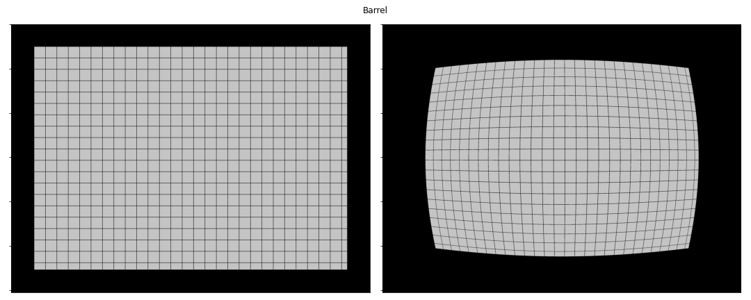
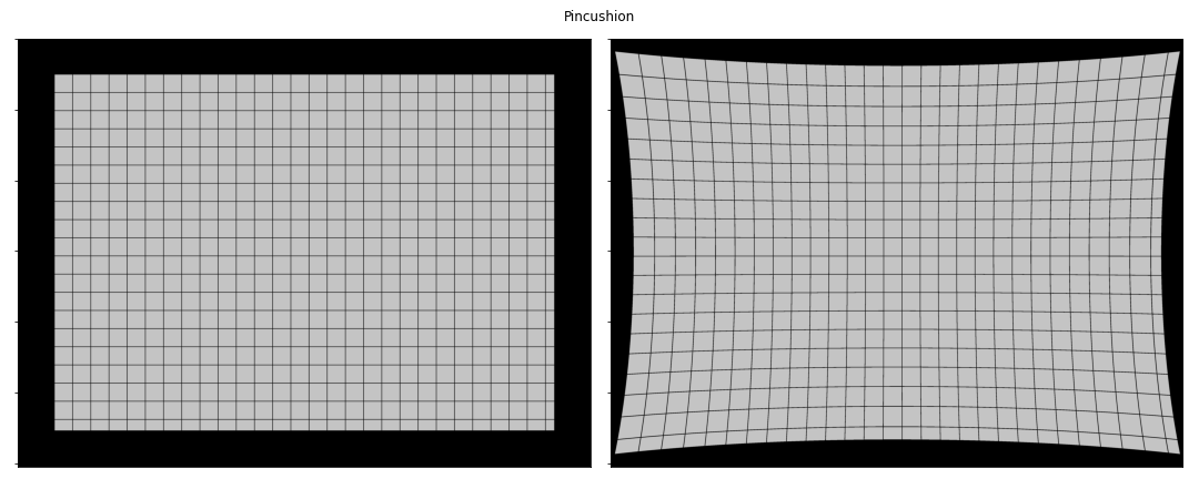
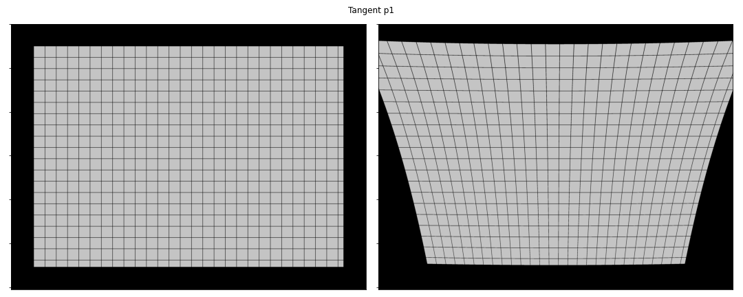
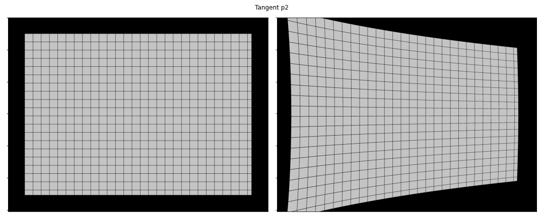
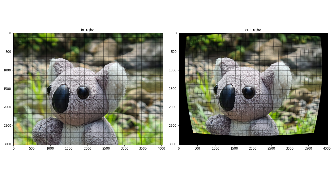
The figures below illustrate the effects of the radial and tangential distortion. A possitive value of $k_1$ creates a barrel effect, while a negative value generates a pincushion effect. For the tangential parameters, $p_1$ models missalignment between the image sensor and the image plane in the $y$ axis, while $p_2$ models such missalignment in the $x$ axis.
Implementation
The camera undistort procedure is implemented as a single ComputeNode with the following interface:
@startuml
skinparam linetype ortho

state CameraUndistort as "CameraUndistort_rgba8ui" {

    state in_rgba <<inputPin>>
    state in_camera <<inputPin>>
    state out_rgba <<outputPin>>

}

note top of CameraUndistort
Parameters
----------
camera_model : int. Defaults to 0.
    The camera model used for rectifying the image. Possible values are:

    * 0: standard model
end note

@enduml
The node explicitly requires rgba8ui images to be bound to the node. The output out_rgba is allocated by the node. The in_camera is a UniformBuffer storing the camera model. This model is defined by the ll_camera struct in GLSL as:
| |
Uniform buffers are a special type of buffers used to store small data structures used in graphics and compute pipelines. The Vulkan tutorial on Uniform Buffers is a good read on how they are used in general. Notice that the ll_camera uses GLSL types such as mat3 and vec4. In the host CPU, one must use corresponding types and follow the byte alignmnet rules to make the buffer usable in the GPU. The alignment rules are defined by the STD140 layout rules. For the ll_camera struct, the mat3 attributes must be transferred as a matrix of 4 rows and 3 columns in order to meet the alignment requirements.
Matrix storage in GLSL
In GLSL, matrices are stored in column-major order. For a given matrixM indexed as M[i, j] where i and j are the row and column indexes, respectively, the elements M[i, j] and M[i, j+1] are stored contiguously in memory. This is different, for instance, to numpy’s default ordering as row-major.The code block below shows a complete example on how to run the lluvia/camera/CameraUndistort_rgba8ui node using a dummy camera model with radial and tangential distortion:
| |
Lines 36 to 60 create the uniform buffer containing the camera model. Lines 42 and 45 create the camera intrinsics matrix K and its inverse Kinv. Then, in lines 50-51, those matrices are aligned to meet the std140 requirements; in this case, storing each matrix in a 4x3 matrix in column-major ordering (using order='F' in numpy). Finally, lines 54-55 concatenates all camera parameters to create a single numpy array npBuf which is then used to create the in_camera uniform buffer in lluvia.
Runtime performance
A Razer Blade laptop running Ubuntu 22.04LTS was used for the runtime analysis. The laptop is equipped with an Intel i7-11800H processor, and the following Vulkan devices as reported by the code block below:
| |
- NVIDIA GeForce RTX 3070 Laptop GPU.
- Intel(R) UHD Graphics (TGL GT1).
- llvmpipe (LLVM 13.0.1, 256 bits). This is a CPU implementation of the Vulkan API shipped with the Mesa drivers.
In addition, the cv2.undistort() function from OpenCV is considered for reference. Five resolutions are used in the evaluation: VGA 640x480, HD 1280x720, FHD 1920x1080, WQHD 2560x1440, and UHD 3840x2160. For each resolution, the algorithm is run for 1000 iterations and the median runtime is extracted. The figure and table belows show the runtime for each device and resolution combination.

| Resolution | Device name | Runtime median ms |
|---|---|---|
| VGA 640x480 | Intel UHD Graphics | 0.00235 |
| RTX 3070 | 0.013888 | |
| llvmpipe | 0.604263 | |
| OpenCV | 2.04252 | |
| HD 1280x720 | Intel UHD Graphics | 0.007734 |
| RTX 3070 | 0.03728 | |
| llvmpipe | 1.50221 | |
| OpenCV | 6.38165 | |
| FHD 1920x1080 | Intel UHD Graphics | 0.0151045 |
| RTX 3070 | 0.07456 | |
| llvmpipe | 3.17916 | |
| OpenCV | 17.1453 | |
| WQHD 2560x1440 | Intel UHD Graphics | 0.0262145 |
| RTX 3070 | 0.109344 | |
| llvmpipe | 5.97528 | |
| OpenCV | 22.8469 | |
| UHD 3840x2160 | Intel UHD Graphics | 0.058583 |
| RTX 3070 | 0.242688 | |
| llvmpipe | 17.6178 | |
| OpenCV | 49.477 |
Integrated vs Discrete GPU performance
Notice that the Intel UHD Graphics device reports lower runtime than the discrete Nvidia RTX 3070 GPU. It is not clear why this is the case, as the Nvidia GPU has more compute resources than the Intel integrated graphics.Also, notice how the llvmpipe CPU device is between three to four times faster than the OpenCV function. However, both CPU devices are 2 orders of magnitude slower than the Nvidia and Intel GPU devices.
Discussion
This post showed how to run the camera undistort node in Lluvia. The node takes as input an RGBA image and a camera model stored in a uniform buffer in the GPU, and produces an RGBA output image. The camera model stored in the uniform model must follow the GLSL std140 layout rules. In terms of runtime performance, the GPU implementation is several orders of magnitude faster than the OpenCV default implementation.
Future pieces of work includes:
- Expose the interpolation coordinates for undistorting the images as a new compute node. These coordinates could be cached in order to save computations on every node invocation.
- Clip the undistorted image to a given area according to the camera model. This will be useful to avoid wasted pixels in the output, as shown in the examples.
- Support for more image formats, such as
r8uiand floating point channel types.
References
- OpenCV camera calibration routines.
- Matlab calibration app.
- Vulkan tutorial on Uniform Buffers.
- GLSL STD140 memory layout.
- Mesa llvmpipe.
- Zhang, Z., 2000. A flexible new technique for camera calibration. IEEE Transactions on pattern analysis and machine intelligence, 22(11), pp.1330-1334. Microsoft Technical Report.
- Wei, G.Q. and De Ma, S., 1994. Implicit and explicit camera calibration: Theory and experiments. IEEE Transactions on Pattern Analysis and Machine Intelligence, 16(5), pp.469-480. DOI.
- Szeliski, R., 2010. Computer vision: algorithms and applications. Springer Science & Business Media. Book.
- Hartley, R. and Zisserman, A., 2003. Multiple view geometry in computer vision. Cambridge university press. Book